
Control Panel Design on Seneca Valley Lines
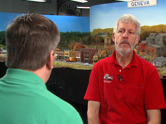
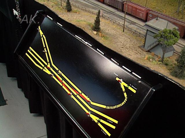
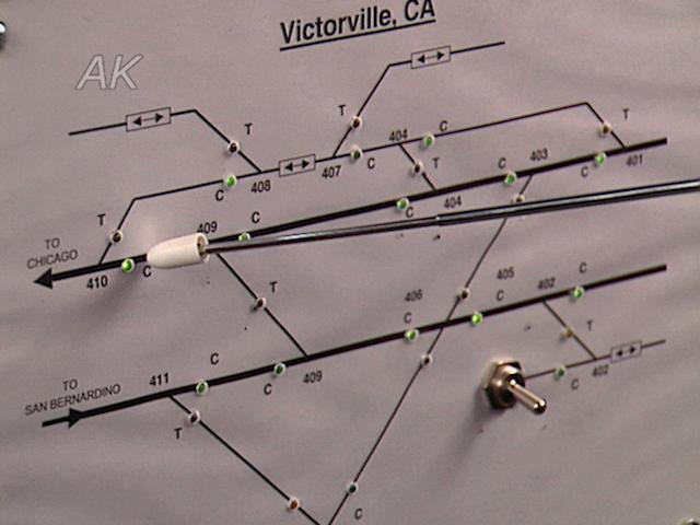
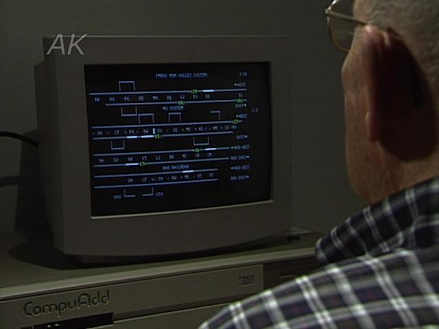
Tom McCullochBill Crocca has been with the Rochester Model Railroad Club for more than 10 years, and is one of two people who work on the electrical parts of the layout. To emulate the Lehigh Valley, they put a control panel every place that the Lehigh Valley would have had a control tower or interlocking tower. He shows a scale drawing of the layout at Victor New York.
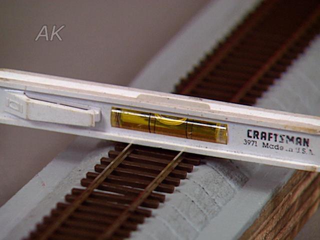
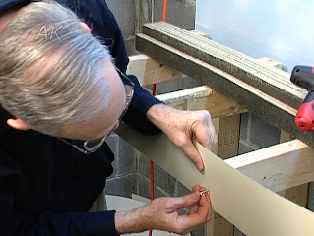
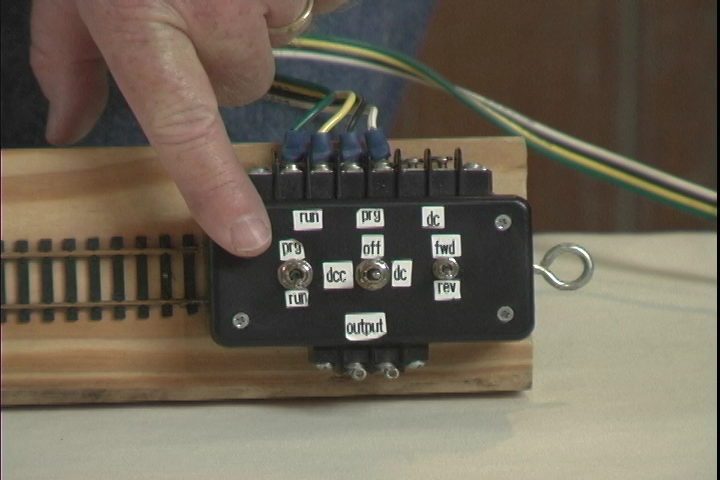
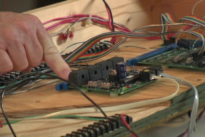
A panel Bill has under construction is made from the drawing previously shown. It starts as a piece of aluminum that’s been painted and then drilled with the holes that locate the various devices. Pinstriping tape has been put over it and finally sealed with a clear coat. Looking at the back of the panel, one can see the indents that are milled in order to make the panel flat enough to mount the devices. The box on which the panel is mounted is intended to recess into the thin facia. The electronics will go inside of this, and then this pivots for building and maintenance.
The graphics were created using tapes from a company called Chart pPack which makes tape for mechanical draftsman and illustrators. The pinstriping tape can be found at an automotive store. Part of the issue when scaling is not only fitting it to the layout physically, but also fitting the components. If the drawing is made too small, the back of the components become too large, and modelers will not be able to get the components close enough. Bill goes on to provide a hint for easily documenting the wiring inside a panel.
To watch more from Allen Keller’s Great Model Railroad series or to learn more about designing a model railway control panel, visit the Model Railroad Academy archives.
Explore videos by Tom McCulloch
You may be interested in

Premium Membership
Unlock exclusive member content from our industry experts.
- 24/7 Access to Premium Model Railroading Videos, Projects, and Tips
- Step-by-Step Instructional Guides & Layout Plans
- 50% Off Video Downloads Purchased in the Model Railroad Academy Shop
- Access to Ask the Expert Program
Unlock exclusive member content from our industry experts.
- 24/7 Access to Premium Model Railroading Videos, Projects, and Tips
- Step-by-Step Instructional Guides & Layout Plans
- 3 Full-Length Video Downloads to Watch Offline
- 50% Off Video Downloads Purchased in the Model Railroad Academy Shop
- Access to Ask the Expert Program
Gold Membership
$326 Value
Get everything included in Premium plus exclusive Gold Membership benefits.
- 24/7 Access to Premium Model Railroading Videos, Projects, and Tips
- Step-by-Step Instructional Guides & Layout Plans
- 9 Full-Length Video Downloads to Watch Offline
- 2 Full-Length Classes to Keep for Life
- 2 Downloadable Guides
- Discounts on Purchase-to-Own Content in the Model Railroad Academy Shop
- Access to Ask the Expert Program
- Exclusive GOLD LIVE Streaming Events