
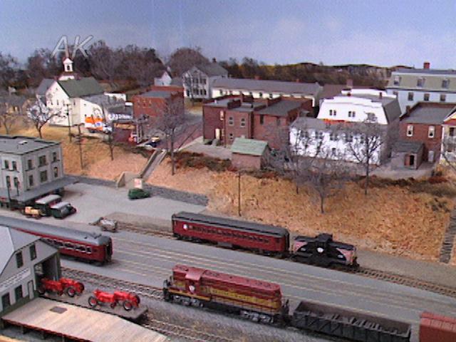
Signal System on the Denver, Front Range & Western
Doug TagsoldThe components used for the signal system on the Denver, Front Range & Western model railroad are readily available parts found at almost any electronic store. The components are a 12 volt miniature relay, a 2-pole 6-position rotary switch, a terminal strip for the wire connections, and any type of signal you want to use.
Inexpensive HO railroad signals will be used for this demonstration. The drawing shown depicts the wiring used for a three throttle system using block control. The power comes from the three wires and the common rail wiring, using one half of the two pole rotary switch. The key to this signal system is a second power supply that is used to power the relays. Each rotary switch alternates from either the plus or minus wire feed coming from the power supply. To complete a circuit between the two rotary switches, both switches have to be lined up for the same throttle.
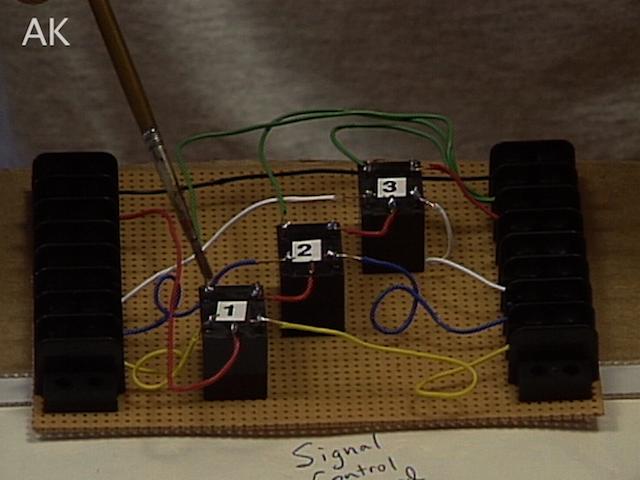
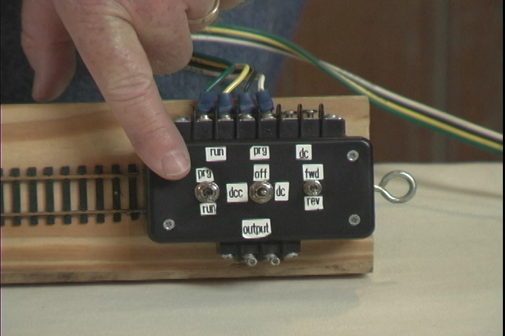
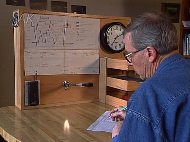
The module shows the wiring that would be needed for the control system. To start, there are the two wires which supply the power from the throttles going to the top half of the rotary switch. For the signal system a red and black wire is added as the power supply for the signals. Below that, the gray and white wires are the power for the relays.
The first rotary switch has the power coming from the gray which is the negative wire. The next switch is connected to the white or positive wire. Going down the layout, the switches would alternate plus or minus. The video goes on to discuss the next module which is the brains of the signal system – the signal control board. You can also learn more about designing a signal system or how to incorporate a signal system.
Explore videos by Doug Tagsold
You may be interested in
Premium Membership
Unlock exclusive member content from our industry experts.
- 24/7 Access to Premium Model Railroading Videos, Projects, and Tips
- Step-by-Step Instructional Guides & Layout Plans
- 50% Off Video Downloads Purchased in the Model Railroad Academy Shop
- Access to Ask the Expert Program
Unlock exclusive member content from our industry experts.
- 24/7 Access to Premium Model Railroading Videos, Projects, and Tips
- Step-by-Step Instructional Guides & Layout Plans
- 3 Full-Length Video Downloads to Watch Offline
- 50% Off Video Downloads Purchased in the Model Railroad Academy Shop
- Access to Ask the Expert Program
Gold Membership
$326 Value
Get everything included in Premium plus exclusive Gold Membership benefits.
- 24/7 Access to Premium Model Railroading Videos, Projects, and Tips
- Step-by-Step Instructional Guides & Layout Plans
- 9 Full-Length Video Downloads to Watch Offline
- 2 Full-Length Classes to Keep for Life
- 2 Downloadable Guides
- Discounts on Purchase-to-Own Content in the Model Railroad Academy Shop
- Access to Ask the Expert Program
- Exclusive GOLD LIVE Streaming Events