
Wiring a Booster Section to Your Layout
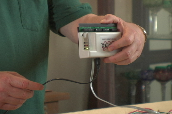
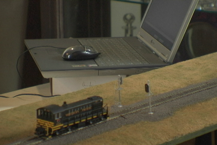
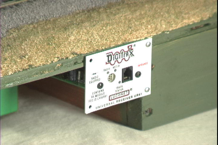
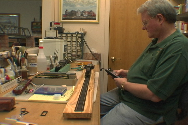
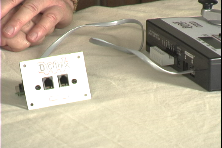
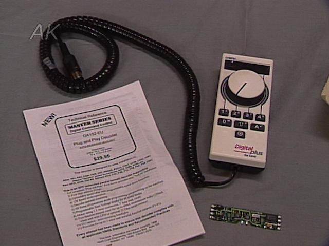
Steve BarkleyModeler and DCC expert Steve Barkley introduces an advanced topic on wiring booster sections for your digital command control station. To better understand what a booster is, Barkley explains it as “a command station without a brain.” It’s a control unit that is slaved to your command station through 6-conductor telephone wire. All digital command stations need at least one booster to work, although most have a built-in booster. The more locomotives you want to run at the same time, the more boosters you need.
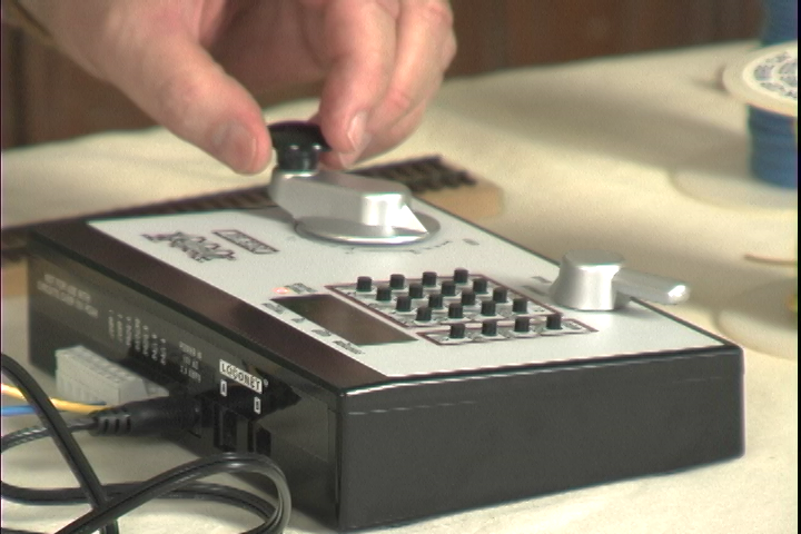
Wiring Your Layout
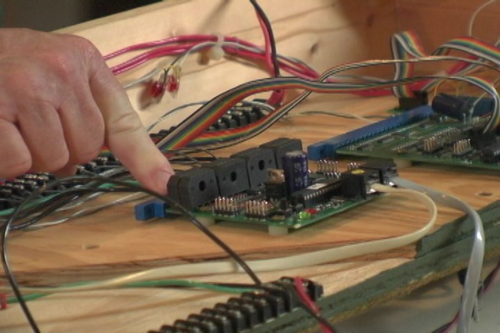
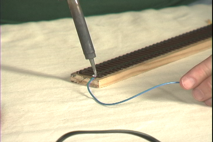
There are two instances when boosters should be used. A booster should be used if there is a section of layout that is physically isolated from the remainder of the layout, as well as when your layout demands more than 5 amps of power. For example, if you have a large layout, you should divide the layout into booster sections. All sections will each be controlled by a booster and all the boosters will be connected using 6-conductor telephone wire and a ground wire.
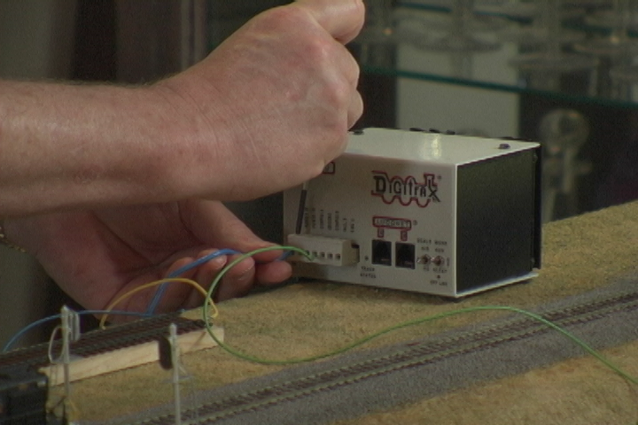
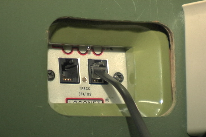
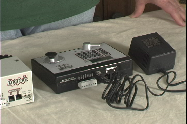
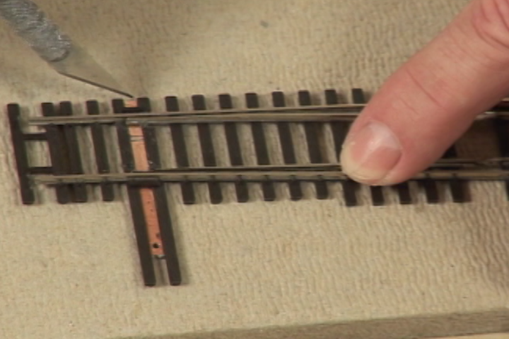
It is important to note that booster sections need to be electrically isolated from the other sections in the layout. The final step in installing your booster is to connect the booster to the command station using the 6-conductor telephone wire. Take on this advanced task alongside Steve Barkley in this Model Railroad Academy video.
Explore videos by Steve Barkley

You may be interested in


Premium Membership
Unlock exclusive member content from our industry experts.
- 24/7 Access to Premium Model Railroading Videos, Projects, and Tips
- Step-by-Step Instructional Guides & Layout Plans
- 50% Off Video Downloads Purchased in the Model Railroad Academy Shop
- Access to Ask the Expert Program
Unlock exclusive member content from our industry experts.
- 24/7 Access to Premium Model Railroading Videos, Projects, and Tips
- Step-by-Step Instructional Guides & Layout Plans
- 3 Full-Length Video Downloads to Watch Offline
- 50% Off Video Downloads Purchased in the Model Railroad Academy Shop
- Access to Ask the Expert Program
Gold Membership
$326 Value
Get everything included in Premium plus exclusive Gold Membership benefits.
- 24/7 Access to Premium Model Railroading Videos, Projects, and Tips
- Step-by-Step Instructional Guides & Layout Plans
- 9 Full-Length Video Downloads to Watch Offline
- 2 Full-Length Classes to Keep for Life
- 2 Downloadable Guides
- Discounts on Purchase-to-Own Content in the Model Railroad Academy Shop
- Access to Ask the Expert Program
- Exclusive GOLD LIVE Streaming Events